Problem
Avid readers will recall a previous post My Mains Monitor, which described a simple circuit designed and built to alert us to mains power failures.
Every so often, the mains power circuit breaker in the van trips for no apparent reason. Sometimes, it even trips for a good reason (air-conditioner + hair dryer + microwave oven + etc. >15 amps). Keeping an absorption fridge at temperature in very hot weather can be challenging. We went to bed one night expecting the relative cool overnight to help get the fridge temp down to something reasonable but woke the next morning to find that the van and hence the fridge had lost mains power sometime during the night.
You may also recall a number of limitations of that design:
- If you leave the monitor turned on when travelling, it flashes and buzzes continuously. If you turn it off but forget to turn it on when you are next connect to mains power, it is a waste of space.
- Depending on the internals of the AC-DC adapter you use, there may be a delay before loss of mains is indicated by the monitor (mine takes about 30 seconds).
- When the input signal is not present, LED1 may be dimly lit.
Needless to say, My Mains Monitor 2.0 solves all of these problems.
- It alerts us to the loss of mains rather than the absence of mains. Whilst the lights indicate the presence or absence of mains, the audible alarm is triggered when previously present mains power becomes absent and can be muted by pushing a button. The mute is then disabled the next time that mains is present so that the next loss of mains will again trigger the alarm.
- The delay before loss of mains is indicated by the monitor is reduced to 2-3 seconds.
- There are no erroneous glimmering LEDs.
Solution
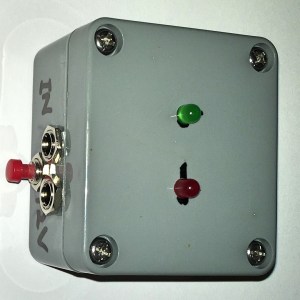
As with version 1, it uses old technology, lights and buzzer, to indicate the condition of the mains. However it is quite different on the inside.
As with v1:
- it is powered from the van battery (even when van is connected to mains);
- it lights a green LED to show that both battery power and mains power are present;
- it takes its “mains on/off” signal from an off-the-shelf AC-DC power adaptor;
- it lights a red LED and sounds a buzzer when mains power is not present;
- it is routinely tested every time that we decamp a powered site and disconnect the mains lead.
But in addition v2.0:
- it has a push button that mutes the buzzer until the next time that the mains power fails, but leaving the red LED on.
Details
For those interested, here is the circuit I used.

Operation
- In essence, it consists of two 555 timers, neither of which are actually used as timers:
- Timer 1 (configured as a Schmitt trigger) conditions the input signal and drives the green and red LEDs, which indicate the presence and absence, respectively of mains power,
- Timer 2 is a set/reset latch (un-clocked flip-flop), which tracks the state of the mute function.
- The monitor is powered from the van’s 12V system and therefore, importantly, from the van’s 12V battery when mains is not connected. I use a short cable between JP1 and one of the van’s “cigarette lighter” sockets.
- A 240V AC to 12V DC adaptor (not shown in schematic above) is plugged into JP2. It provides safety isolation of the monitor from the high voltage AC mains supply as well as a conveniently low voltage DC signal that indicates the presence or absence of mains power.
- The voltage divider RV1 is adjusted to reduce the input signal voltage from 12V (or whatever the AC-DC adaptor provides) to approximately 9V .
- R4 & R5 are current-limiting resistors for LED1 & LED2, respectively.
- Jumper JP3 is normally shunted; removing the shunt permanently mutes the buzzer without affecting the LEDs.
- When the mains power input signal is present:
- Timer 1 is reset by the high (9V) signal applied to its Threshold input TRES1, so
- output OUT1 goes low, lighting LED1 rather than LED2,
- Timer 2 is reset, leaving it ready for the next power failure;
- When the mains power input signal is not present:
- Timer 1 is set by the low signal applied to its active-low Trigger input (TRIG1), so
- output OUT1 goes high, lighting LED2;
- if Timer 2 is currently reset, its output OUT2 is low, so
- diode D1 is forward-biased and hence conducts, so
- the Buzzer (SG1) sounds;
- SW1 is an SPST momentary contact switch. While it is not pressed,
- Timer 2’s Trigger input (TRIG2) is pulled high by R2 so TRIG2 is not active;
- When the SW1 is pressed,
- Timer 2 is set by the low signal applied to its active-low Trigger input (TRIG2), so
- its output OUT2 goes high, so
- diode D1 is reverse-biased and hence does not conduct, so
- the Buzzer stops sounding.
- When the push button is released,
- Timer 2 remains set, suppressing the buzzer until the mains power is restored, when
- Timer2 is reset by TRES2 going high.
Notes
- Diode D1 effectively provides the logical function “OUT1 AND NOT OUT2”.
- Resistor R3 and electrolytic capacitor C3 ensure that both timers are reset at power-on. When C3 starts charging at power-on, POR is low, resetting both timers via their active-low RESET inputs. When C3 is sufficiently charged, junction POR goes high so the reset inputs are no longer active.
- Capacitors C1 and C2 are considered to be good housekeeping for 555 timers.
Parts
- for the 555 timers, I used an NE566, which is a pair of 555 timers in one 14 pin DIP package;
- JP1 is a socket chosen to suit the cable that you use to connect to 12V battery power: I used a cable with a cigarette lighter plug on one end and a 2.1mm plug on the other so my JP1 is also a 2.1mm socket;
- JP2 is a socket chosen to suit your AC-DC adaptor, in my case JP2 is also a 2.1mm socket;
- my B1 is a 9-14V DC buzzer (Jaycar part AB3459); any noisemaker that works with 12VDC and does not draw more than 200mA should do it (maximum source current of OUT1 is 225mA, less 20mA for LED2);
- for LED1, I used a green, 5mm LED (Jaycar part ZD0150)
- for SW1 and LED2, I used a push button with integrated red LED (similar to Altronics S1063 or Jaycar Part SP0706);
- for diode D1, I used an IN4148 signal diode (Jaycar part ZR1100); any diode with a maximum reverse voltage of 15V or more and a maximum forward current of at least the current drawn by the combination of buzzer B1 and LED2; if in doubt, use any power (rectifier) diode ;
- the value of R4 and R3 should be chosen to suit your choice of LED1 and LED2, respectively, when used with a 12V supply;
- for RV1, I used a 10K x 20-turn variable resistor: anything from 1K to 100K should work;
- R1 is a load resistor whose purpose is to more rapidly discharge stored voltage in the AC-DC when the mains power fails: in my case adding R1 reduced that time from 20-30 seconds to 2-3 seconds;
- for the enclosure I used an ABS plastic box (Jaycar part HB6120);
- the board was cut from a piece of Pre-Punched Experimenter Board (such as Jaycar part HP9550).
Construction
If you read this far, you probably know how to solder all of that onto a board and put it into a box. Here are some internal pictures of mine.


Notes
- The unusual PCB shape was cut to fit the enclosure.
- The black, cylindrical component is the buzzer.
- The LEDs are glued using epoxy-resin into holes drilled in the lid of the box.
- Pairs of breakaway header pins on the board and wire pairs with female sockets on one end are used to connect the LEDs and sockets to the board. (I used female-female breadboard wires cut in half.)
- The ink doodling on the board indicates location of the Vcc+ and ground rails on the underside
- Spots of coloured nail polish reminder me which header pins are which:
- red and black for Vcc+ and GND,
- yellow and black for Vin and GND.
Side Bar: The NE555
Developed in 1971, the 555 timer is reputedly the most popular integrated circuit (IC) ever invented, with billions of units manufactured each year.
Although designed and labelled as a timer, it is arguably a box of useful parts, some applications of which are timers. Those parts include:
- a set/reset latch (flip-flop),
- two (2) comparators driving the set/reset inputs of the latch,
- a resistor divider network of three (5K) resistors in series providing reference voltages of 1/3 Vcc and 2/3 Vcc to the comparators,
- an output driver that can both source and sink approximately 200mA.
It can be configured as a monostable, bistable or astable multivibrator. When used as an astable or monostable multivibrator, it is combined with an external timing capacitor and resistors, which determine its timing parameters. This project uses both “timers” in bistable mode, which does not require external timing components.
There have many books, blogs, etc. published about applications for the 555. The following are just some that provide an introduction.
- https://en.wikipedia.org/wiki/555_timer_IC
- http://www.electronics-tutorials.ws/waveforms/555_timer.html
- http://www.555-timer-circuits.com
- NE555 datasheet
- NE556 datasheet
- The 555 TIMER IC – An Interview with Hans Camenzind
Next Episode
Coming up next is a Three-Way Fridge Monitor. Or maybe something else …
-Tim.